Section on how to create Basic volmdlr objects#
Basic Objects#
How to create a Vector#
To instantiate the Vector, you need to provide the required arguments. In this case, the constructor expects two mandatory arguments x and y for the 2-dimensional vector, and an additional argument z for the 3-dimensional vector, which are floats representing the vector’s coordinates. Additionally, there is an optional argument name, which is a string representing the vector’s name.
import volmdlr
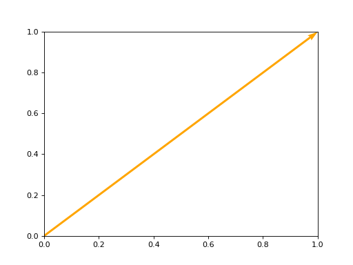
vector = volmdlr.Vector2D(1.0, 1.0)
vector.plot(color='orange')
(Source code, png, hires.png, pdf)
import volmdlr
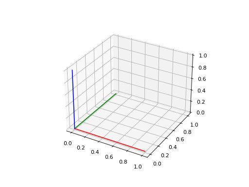
vector = volmdlr.Vector3D(1.0, 1.0, 1.0)
vector.plot(color='orange')
How to create a Point#
Point 2D#
To instantiate the Point2D class, you need to provide the two mandatory arguments required x and y, which are both floats representing the vector’s coordinates. Additionally, there is an optional argument name, which is a string representing the vector’s name.
import volmdlr

point2d = volmdlr.Point2D(x=1.0, y=2.0, name='vector name')
print('point2d:', point2d)
>>> point2d: Point2D: [1.0, 2.0]
Point 3D#
To instantiate the Point3D class, you need to provide three mandatory arguments required x, y, z which are floats representing the vector’s coordinates. Additionally, there is an optional argument name, which is a string representing the vector’s name.
import volmdlr

point3d = volmdlr.Point3D(x=1.0, y=2.0, z=3.0, name='vector name')
print('point3d:', point3d)
>>> point2d: Point3D: [1.0, 2.0, 3.0]
How to create a Frame3D#
The given class Frame3D represents a 3D frame. It defines a frame by specifying its origin point and three basis vectors (u, v, and w) that determine the orientation of the frame.
Exmaple:
import volmdlr

origin = volmdlr.Point3D(0, 0, 0)
u = volmdlr.Vector3D(1, 0, 0)
v = volmdlr.Vector3D(0, 1, 0)
w = volmdlr.Vector3D(0, 0, 1)
frame = volmdlr.Frame3D(origin, u, v, w)
frame.plot()
(Source code, png, hires.png, pdf)
Curves#
How to create Line in 2D and 3D#
Line2D and Line3D represents an infinite lines in both 2 and 3D that passes through two points. They are a subclass of Line, which handles line-related operations. The class takes two Point objects as inputs to define the line and an optional name for identification.
To instantiate then, you need to create an object of of the corresponding class by calling its constructor (__init__) and providing the required arguments. Here’s how you can do it:
import volmdlr
from volmdlr import curves
from volmdlr.core import EdgeStyle
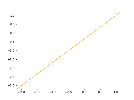
point1 = volmdlr.Point2D(1.0, 1.0)
point2 = volmdlr.Point2D(-2.0, -3.0)
line2d = curves.Line2D(point1, point2, name='line2d_name_is_optional')
line2d.plot(edge_style=EdgeStyle('orange'))
(Source code, png, hires.png, pdf)
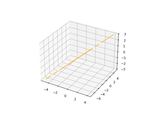
import volmdlr
from volmdlr import curves
from volmdlr.core import EdgeStyle

point1 = volmdlr.Point3D(1.0, 1.0, 1.0)
point2 = volmdlr.Point3D(-2.0, -3.0, -1.0)
line3d = curves.Line3D(point1, point2, name='line3d_name_is_optional')
line3d.plot(edge_style=EdgeStyle('orange'))
(Source code, png, hires.png, pdf)
How to create a Circle#
Circle2D#
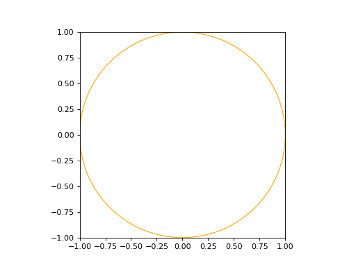
The circle2d is defined by its center point (Point2D) and a radius (float), and it also accepts an optional name for identification.
import volmdlr
from volmdlr import curves
from volmdlr.core import EdgeStyle

center2d = volmdlr.Point2D(0.0, 0.0)
circle2d = curves.Circle2D(frame=volmdlr.OXY, radius=1, name='optional_circle_name')
circle2d.plot(edge_style=EdgeStyle('orange'))
(Source code, png, hires.png, pdf)
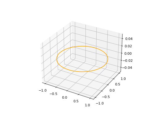
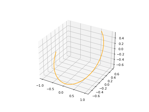
Circle3D#
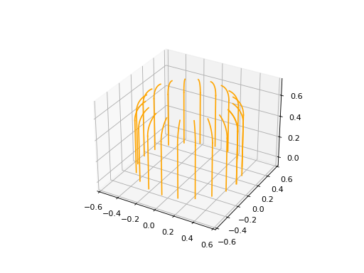
The circle is defined by a Frame3D object that includes information about the center and orientation of the circle in 3D space, along with a radius (float). The frame’s u and v vectors define the plane in which the circle lies, and w represents the normal vector to the plane.
import volmdlr
from volmdlr import curves
from volmdlr.core import EdgeStyle

center3D = volmdlr.Point3D(0.0, 0.0, 0.0)
u_vector = volmdlr.Vector3D(1.0, 0.0, 0.0)
v_vector = volmdlr.Vector3D(0.0, 1.0, 0.0)
w_vector = volmdlr.Vector3D(0.0, 0.0, 1.0)
frame3d = volmdlr.Frame3D(center3D, u_vector, v_vector, w_vector)
circle3d = curves.Circle3D(frame=frame3d, radius=1, name='optional_circle_name')
circle3d.plot(edge_style=EdgeStyle('orange'))
(Source code, png, hires.png, pdf)
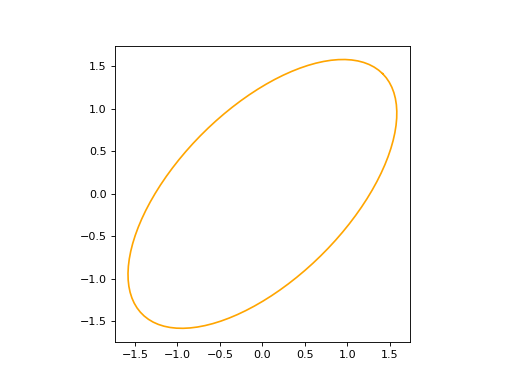
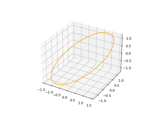
How to create an Ellipse#
An ellipse in defined by three arguments: a major axis (A), e minor axis (B) and a Frame (2D or 3D).
import volmdlr
from volmdlr import curves
from volmdlr.core import EdgeStyle

u_vector = volmdlr.Vector2D(0.7071067811865475, 0.7071067811865475)
v_vector = volmdlr.Vector2D(-0.7071067811865475, 0.7071067811865475)
ellipse2d = curves.Ellipse2D(major_axis=2, minor_axis=1, frame=volmdlr.Frame2D(volmdlr.O2D, u_vector, v_vector))
ellipse2d.plot(edge_style=EdgeStyle(color='orange'))
(Source code, png, hires.png, pdf)
import volmdlr
from volmdlr import curves
from volmdlr.core import EdgeStyle

vector1 = volmdlr.Vector3D(1, 1, 1)
vector1 = vector1.unit_vector()
vector2 = vector1.deterministic_unit_normal_vector()
vector3 = vector1.cross(vector2)
frame = volmdlr.Frame3D(volmdlr.O3D, vector1, vector2, vector3)
ellipse3d = curves.Ellipse3D(major_axis=2, minor_axis=1, frame=frame)
ellipse3d.plot(edge_style=EdgeStyle('orange'))
(Source code, png, hires.png, pdf)
How to create an Hyperbola#
A Hyperbola in defined by three arguments: a frame (2D or 3D), a semi major axis and a semi minor axis. For more details on Hyperbolas, you can search for the corresponding class in Curves:.
import volmdlr
from volmdlr import curves
from volmdlr.core import EdgeStyle

hyperberbola_2d = curves.Hyperbola2D(volmdlr.OXY, 1, 2)
hyperberbola_2d.plot(edge_style=EdgeStyle(color='orange'))
(Source code, png, hires.png, pdf)
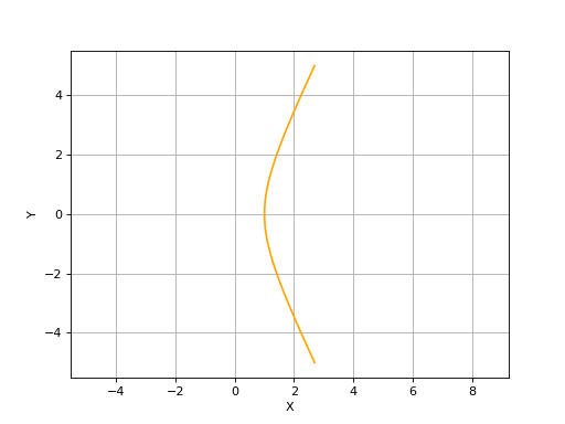
import volmdlr
from volmdlr import curves
from volmdlr.core import EdgeStyle

hyperberbola_3d = curves.Hyperbola3D(volmdlr.OXYZ, 1, 2)
hyperberbola_3d.plot(edge_style=EdgeStyle(color='orange'))
(Source code, png, hires.png, pdf)
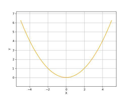
How to create an Parabola#
A Parabola in defined by two arguments: a frame (2D or 3D) and the focal length value. There’s also an optional name parameter. For more details on Parabolas, you can search for the corresponding class in Curves:.
import volmdlr
from volmdlr import curves
from volmdlr.core import EdgeStyle

parabola_2d = curves.Parabola2D(volmdlr.OXY, 1)
parabola_2d.plot(edge_style=EdgeStyle(color='orange'))
(Source code, png, hires.png, pdf)
import volmdlr
from volmdlr import curves
from volmdlr.core import EdgeStyle

parabola_3d = curves.Parabola3D(volmdlr.OXYZ, 2)
parabola_3d.plot(edge_style=EdgeStyle(color='orange'))
(Source code, png, hires.png, pdf)
Edges#
How to create a LineSegment#
To instanciate a LineSegment in 2D or 3D, you will need to provide two mandatory arguments, the start and end points. Additionally you will have two optional arguments: an infinite line which the line segment lies on and a name argument.
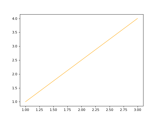
LineSegment2D#
import volmdlr
from volmdlr import edges
from volmdlr.core import EdgeStyle

start_point = volmdlr.Point2D(1.0, 1.0)
end_point = volmdlr.Point2D(3.0, 4.0)
linesegment2d = edges.LineSegment2D(start=start_point, end=end_point, name='linesegment\'s name')
linesegment2d.plot(edge_style=EdgeStyle(color='orange'))
(Source code, png, hires.png, pdf)
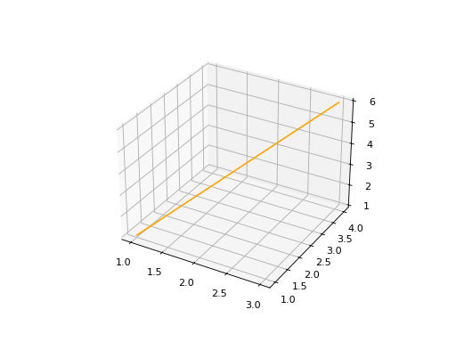
LineSegment3D#
import volmdlr
from volmdlr import edges
from volmdlr.core import EdgeStyle

start_point = volmdlr.Point3D(1.0, 1.0, 1.0)
end_point = volmdlr.Point3D(3.0, 4.0, 6.0)
linesegment3d = edges.LineSegment3D(start=start_point, end=end_point, name='linesegment\'s name')
linesegment3d.plot(edge_style=EdgeStyle(color='orange'))
(Source code, png, hires.png, pdf)
How to create an Arc#
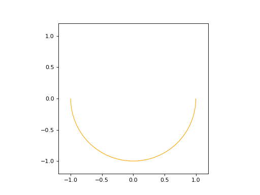
Arc2D#
An Arc2D is defined by the base circle curve along with a start and end points. There is also a boolean is_trigo argument that defines if the arc is in the trigo-wise direction or not and a last and optional name argument.
import volmdlr
from volmdlr import edges, curves
from volmdlr.core import EdgeStyle

circle2d = curves.Circle2D(volmdlr.OXY, 1)
arc2d = edges.Arc2D(circle2d, volmdlr.Point2D(-1, 0), volmdlr.Point2D(1, 0), True)
ax = arc2d.plot(edge_style=EdgeStyle('orange'))
ax.set_aspect('equal')
(Source code, png, hires.png, pdf)
Arc3D#
Just as the Arc2D, Arc3D is defined by the base circle curve along with a start and end points. There is also an optional name argument.
import volmdlr
from volmdlr import edges, curves
from volmdlr.core import EdgeStyle

vector1 = volmdlr.Vector3D(1, 1, 1)
vector1 = vector1.unit_vector()
vector2 = vector1.deterministic_unit_normal_vector()
vector3 = vector1.cross(vector2)
frame = volmdlr.Frame3D(volmdlr.O3D, vector1, vector2, vector3)
circle3d = curves.Circle3D(frame, 1)
arc3d = edges.Arc3D(circle3d, start=volmdlr.Point3D(0.5773502691896258, 0.5773502691896258, 0.5773502691896258),
            end=volmdlr.Point3D(-0.9855985596534886, -0.11957315586905026, -0.11957315586905026))
ax = arc3d.plot(edge_style=EdgeStyle('orange'))
(Source code, png, hires.png, pdf)
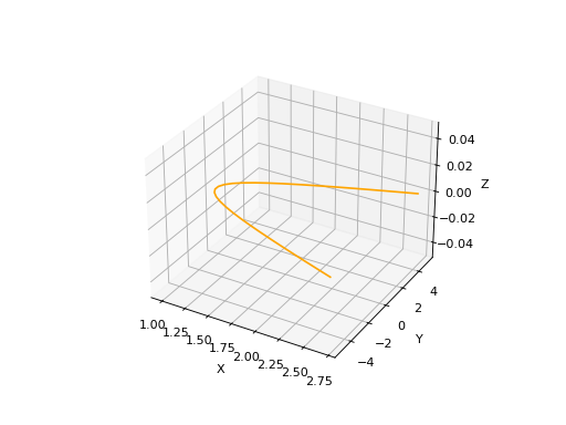
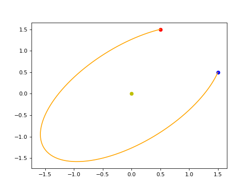
How to create an ArcEllipse#
Both ArcEllipse2D and ArcEllipse3D require a base Ellipse curve along with a start end end points. There also an optional name argument.
ArcEllipse2D#
Object’s descrition
import volmdlr
from volmdlr import edges, curves
from volmdlr.core import EdgeStyle

u_vector = volmdlr.Vector2D(0.7071067811865475, 0.7071067811865475)
v_vector = volmdlr.Vector2D(-0.7071067811865475, 0.7071067811865475)
ellipse2d = curves.Ellipse2D(2, 1, volmdlr.Frame2D(volmdlr.O2D, u_vector, v_vector))
u_vector = volmdlr.Vector2D(0.7071067811865475, 0.7071067811865475)
v_vector = volmdlr.Vector2D(-0.7071067811865475, 0.7071067811865475)
ellipse2d = curves.Ellipse2D(2, 1, volmdlr.Frame2D(volmdlr.O2D, u_vector, v_vector))
arc_ellipse2d = edges.ArcEllipse2D(ellipse2d, start=volmdlr.Point2D(0.5, 1.5), end=volmdlr.Point2D(1.5, 0.5))
arc_ellipse2d.plot(edge_style=EdgeStyle('orange'))
(Source code, png, hires.png, pdf)
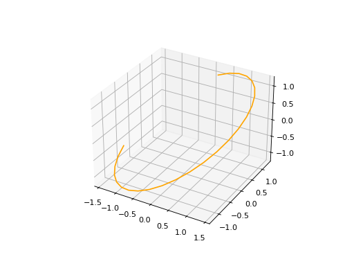
ArcEllipse3D#
Object’s descrition
import volmdlr
from volmdlr import edges, curves
from volmdlr.core import EdgeStyle

vector1 = volmdlr.Vector3D(1, 1, 1)
vector1 = vector1.unit_vector()
vector2 = vector1.deterministic_unit_normal_vector()
vector3 = vector1.cross(vector2)
frame = volmdlr.Frame3D(volmdlr.O3D, vector1, vector2, vector3)
start_point = volmdlr.Point3D(0.2391463117381003, 1.1051717155225391, 1.1051717155225391)
end_point = volmdlr.Point3D(-1.393846850117352, -0.5278214463329132, -0.5278214463329132)
ellipse3d = curves.Ellipse3D(2, 1, frame)
arc_ellipse3d = edges.ArcEllipse3D(ellipse3d, start=start_point, end=end_point)
arc_ellipse3d.plot(edge_style=EdgeStyle('orange'))
(Source code, png, hires.png, pdf)
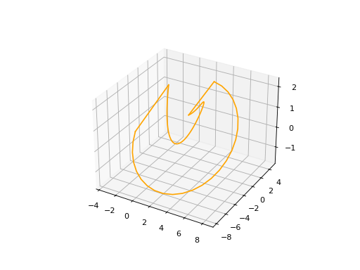
How to create a BSplineCurve#
To instanciate a BsplineCurve 2D or 3D, we must provide the necessary parameters, such as the degree, control points, knot multiplicities, knot vector, and optional weights and name.
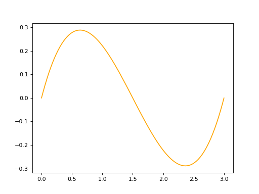
BSplineCurve2D#
import volmdlr
from volmdlr import edges
from volmdlr.core import EdgeStyle
from geomdl import utilities

DEGREE = 3
points = [volmdlr.Point2D(0, 0), volmdlr.Point2D(1, 1), volmdlr.Point2D(2, -1), volmdlr.Point2D(3, 0)]
knotvector = utilities.generate_knot_vector(DEGREE, len(points))
knot_multiplicity = [1] * len(knotvector)
bspline1 = edges.BSplineCurve2D(DEGREE, points, knot_multiplicity, knotvector, None, False)
bspline1.plot(edge_style=EdgeStyle('orange'))
(Source code, png, hires.png, pdf)
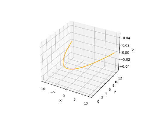
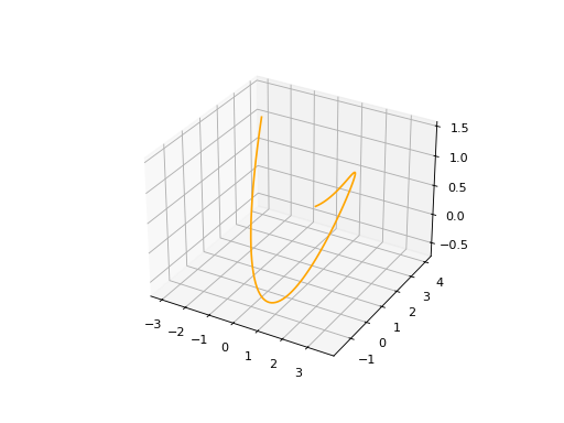
BSplineCurve3D#
import volmdlr
from volmdlr import edges
from volmdlr.core import EdgeStyle

degree = 5
control_points = [volmdlr.Point3D(0, 3, 0),
                  volmdlr.Point3D(3, 2, 1),
                  volmdlr.Point3D(5, -1, 4),
                  volmdlr.Point3D(5, -4, 0),
                  volmdlr.Point3D(-1, -2, -3),
                  volmdlr.Point3D(-3, 4, 1)]
knots = [0.0, 1.0]
knot_multiplicities = [6, 6]
weights = None  # [1, 2, 1, 2, 1, 2]
bspline_curve3d = edges.BSplineCurve3D(degree=degree, control_points=control_points,
                                knot_multiplicities=knot_multiplicities,
                                knots=knots,
                                weights=weights,
                                name='B Spline Curve 3D 1')
bspline_curve3d.plot(edge_style=EdgeStyle('orange'))
(Source code, png, hires.png, pdf)
Wires#
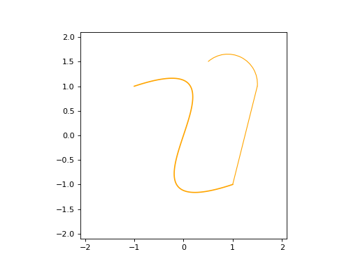
How to create a Wire#
A wire is an object composed of a list of primitives that does not form a closed and an optional name. This primitives list can contain any set of edges following each other.
Wire2D#
import volmdlr
from volmdlr import wires, edges
from volmdlr.core import EdgeStyle

line_segment1 = edges.LineSegment2D(volmdlr.Point2D(1, -1), volmdlr.Point2D(1.5, 1))
arc = edges.Arc2D.from_3_points(volmdlr.Point2D(1.5, 1), volmdlr.Point2D(1.3, 1.5), volmdlr.Point2D(0.5, 1.5))
points2d = [volmdlr.Point2D(-1, 1), volmdlr.Point2D(2, 2), volmdlr.Point2D(-2, -2), volmdlr.Point2D(1, -1)]
bspline = edges.BSplineCurve2D(3, points2d, knot_multiplicities=[4, 4], knots=[0.0, 1.0])
wire2d = wires.Wire2D([bspline, line_segment1, arc])
wire2d.plot(edge_style=EdgeStyle('orange'))
(Source code, png, hires.png, pdf)
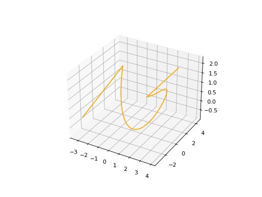
Wire3D#
import volmdlr
from volmdlr import edges, wires
from volmdlr.core import EdgeStyle

degree = 5
control_points = [volmdlr.Point3D(0, 3, 0),
                 volmdlr.Point3D(3, 2, 1),
                 volmdlr.Point3D(5, -1, 4),
                 volmdlr.Point3D(5, -4, 0),
                 volmdlr.Point3D(-1, -2, -3),
                 volmdlr.Point3D(-3, 4, 1)]
knots = [0.0, 1.0]
knot_multiplicities = [6, 6]
weights = None  # [1, 2, 1, 2, 1, 2]
bspline_curve3d = edges.BSplineCurve3D(degree=degree, control_points=control_points,
                               knot_multiplicities=knot_multiplicities,
                               knots=knots,
                               weights=weights,
                               name='B Spline Curve 3D 1')
lineseg1 = edges.LineSegment3D(volmdlr.Point3D(3, 3, 2), bspline_curve3d.start)
lineseg2 = edges.LineSegment3D(bspline_curve3d.end, volmdlr.Point3D(-3, -3, 0))
wire3d = wires.Wire3D([lineseg1, bspline_curve3d, lineseg2])
wire3d.plot(edge_style=EdgeStyle('orange'))
(Source code, png, hires.png, pdf)
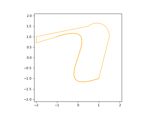
How to create a Contour#
As a wire, A contour is also an object composed of a list of primitives but now it forms a closed loop. The optional name argument is always present. The primitives list can contain any set of edges following each other.
Contour2D#
import volmdlr
from volmdlr import edges, wires
from volmdlr.core import EdgeStyle

line_segment1 = edges.LineSegment2D(volmdlr.Point2D(1, -1), volmdlr.Point2D(1.5, 1))
line_segment2 = edges.LineSegment2D(volmdlr.Point2D(0.5, 1.5), volmdlr.Point2D(-2, 1))
line_segment3 = edges.LineSegment2D(volmdlr.Point2D(-2, 1), volmdlr.Point2D(-2, 0.7))
line_segment4 = edges.LineSegment2D(volmdlr.Point2D(-2, 0.7), volmdlr.Point2D(-1, 1))
arc = edges.Arc2D.from_3_points(volmdlr.Point2D(1.5, 1), volmdlr.Point2D(1.3, 1.5), volmdlr.Point2D(0.5, 1.5))
points2d = [volmdlr.Point2D(-1, 1), volmdlr.Point2D(2, 2), volmdlr.Point2D(-2, -2), volmdlr.Point2D(1, -1)]
bspline = edges.BSplineCurve2D(3, points2d, knot_multiplicities=[4, 4], knots=[0.0, 1.0])
wire2d = wires.Wire2D([bspline, line_segment1, arc, line_segment2, line_segment3, line_segment4])
wire2d.plot(edge_style=EdgeStyle('orange'))
(Source code, png, hires.png, pdf)
Contour3D#
import volmdlr
from volmdlr import edges, wires
from volmdlr.core import EdgeStyle

degree = 5
control_points = [volmdlr.Point3D(0, 3, 0),
                 volmdlr.Point3D(3, 2, 1),
                 volmdlr.Point3D(5, -1, 4),
                 volmdlr.Point3D(5, -4, 0),
                 volmdlr.Point3D(-1, -2, -3),
                 volmdlr.Point3D(-3, 4, 1)]
knots = [0.0, 1.0]
knot_multiplicities = [6, 6]
weights = None  # [1, 2, 1, 2, 1, 2]
bspline_curve3d = edges.BSplineCurve3D(degree=degree, control_points=control_points,
                               knot_multiplicities=knot_multiplicities,
                               knots=knots,
                               weights=weights,
                               name='B Spline Curve 3D 1')
lineseg1 = edges.LineSegment3D(volmdlr.Point3D(3, 3, 2), bspline_curve3d.start)
lineseg2 = edges.LineSegment3D(bspline_curve3d.end, volmdlr.Point3D(-3, -3, 0))
arc = edges.Arc3D.from_3_points(volmdlr.Point3D(-3, -3, 0), volmdlr.Point3D(6.324555320336761, -5.692099788303083, -0.8973665961010275), volmdlr.Point3D(3, 3, 2))
wire3d = wires.Wire3D([lineseg1, bspline_curve3d, lineseg2, arc])
wire3d.plot(edge_style=EdgeStyle('orange'))
(Source code, png, hires.png, pdf)
Surfaces#
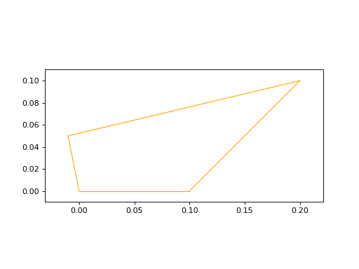
Surface2D#
To create a Surface2D, you need to provide two arguments: a outer_contour and a inner_contours and an optional name parameter.
Attributes: outer_contour: This is a parameter passed to the constructor representing the outer boundary or contour of the surface. It is of type wires.Contour2D, which is a series of connected points that form a closed loop.
inner_contours: This is a parameter representing a list of inner contours within the surface. It is of type List[wires.Contour2D], indicating that there can be multiple inner contours. Inner contours could represent holes or cutouts within the surface.
name: An optional parameter representing the name of the surface. The default value is set to ‘name’ if not provided.
import volmdlr
from volmdlr import surfaces
from volmdlr.core import EdgeStyle

p1s = volmdlr.Point2D(0, 0)
p2s = volmdlr.Point2D(0.1, 0)
p3s = volmdlr.Point2D(0.2, 0.1)
p4s = volmdlr.Point2D(-0.01, 0.05)
surface2d = surfaces.Surface2D(volmdlr.wires.ClosedPolygon2D([p1s, p2s, p3s, p4s]), [])
surface2d.plot(edge_style=EdgeStyle('orange'))
(Source code, png, hires.png, pdf)
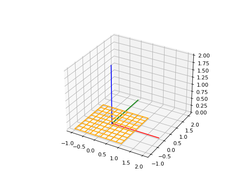
Plane3D#
Plane3D represents a three-dimensional plane. To build it, it is needed a frame and an optinal name paramenter.
frame: This is a parameter passed to the constructor, representing a three-dimensional frame that describes the plane. The frame consists of an origin o and vectors u and v that define the plane, and w represents the normal vector to the plane. This implies that the plane is defined by a local coordinate system.
name: An optional parameter representing the name of the plane. The default value is an empty string if not provided.
import volmdlr
from volmdlr import edges, curves, surfaces, wires, faces
from volmdlr.core import EdgeStyle

surface3d = surfaces.Plane3D(volmdlr.Frame3D(volmdlr.Point3D(0.0, 0.0, 0.0), volmdlr.Vector3D(1.0, 0.0, 0.0),
                                            volmdlr.Vector3D(0.0, 1.0, 0.0), volmdlr.Vector3D(0.0, 0.0, 1.0)))
surface3d.plot(edge_style=EdgeStyle('orange'), length=2)
(Source code, png, hires.png, pdf)
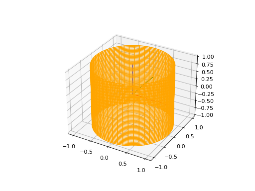
CylindricalSurface3D#
To instanciate a CylindricalSurface3D, you have to provide tree parameters: a frame, a radius, and an optional name.
frame: This is a parameter passed to the constructor, representing a three-dimensional frame that describes the plane. The frame consists of an origin o and vectors u and v that define the plane, and w represents the normal vector to the plane. This implies that the plane is defined by a local coordinate system.
radius: The Cylinder radius.
name: An optional parameter representing the name of the plane. The default value is an empty string if not provided.
import volmdlr
from volmdlr import surfaces
from volmdlr.core import EdgeStyle

surface3d = surfaces.CylindricalSurface3D(volmdlr.OXYZ, 1, 'cylindrical_surface_name')
surface3d.plot(edge_style=EdgeStyle('orange'), length=2)
(Source code, png, hires.png, pdf)
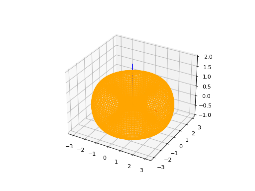
ToroidalSurface3D#
To instanciate a ToroidalSurface3D, you have to provide tree parameters: a frame, a major_radius, a minor_radius and an optional name.
frame: This is a parameter passed to the constructor, representing a three-dimensional frame that describes the plane. The frame consists of an origin o and vectors u and v that define the plane, and w represents the normal vector to the plane. This implies that the plane is defined by a local coordinate system.
major_radius: The torus major radius.
minor_radius: The torus minor radius.
name: An optional parameter representing the name of the plane. The default value is an empty string if not provided.
import volmdlr
from volmdlr import surfaces
from volmdlr.core import EdgeStyle
surface3d = surfaces.ToroidalSurface3D(frame=volmdlr.OXYZ, major_radius=2, minor_radius=1, name='toroidal_surface_name')
surface3d.plot(edge_style=EdgeStyle('orange'), length=2)
(Source code, png, hires.png, pdf)
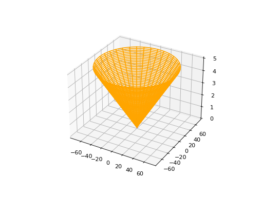
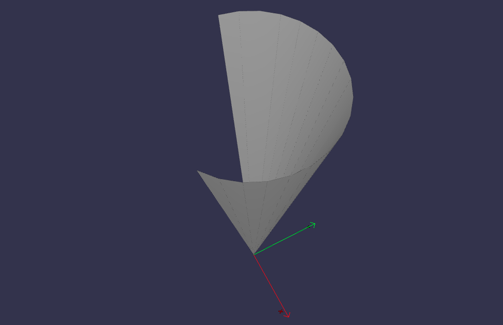
ConicalSurface3D#
To instanciate a ConicalSurface3D, you have to provide tree parameters: a frame, a angle and an optional name parameter.
frame: This is a parameter passed to the constructor, representing a three-dimensional frame that describes the plane. The frame consists of an origin o and vectors u and v that define the plane, and w represents the normal vector to the plane. This implies that the plane is defined by a local coordinate system.
semi_angle: This is a parameter represents the semi-angle of the cone. The semi-angle defines the opening of the cone.
name: An optional parameter representing the name of the plane. The default value is an empty string if not provided.
import volmdlr
from volmdlr import surfaces
from volmdlr.core import EdgeStyle

surface3d = surfaces.ConicalSurface3D(frame=volmdlr.OXYZ, semi_angle=1.5, name='conical_surface_name')
surface3d.plot(edge_style=EdgeStyle('orange'), z=5)
(Source code, png, hires.png, pdf)
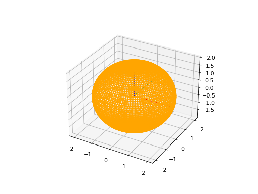
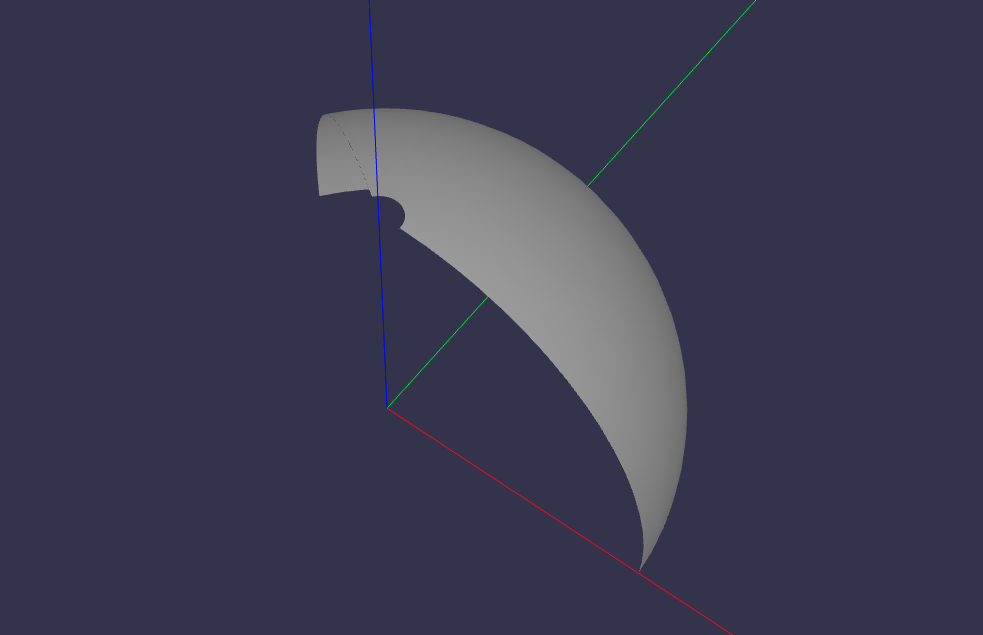
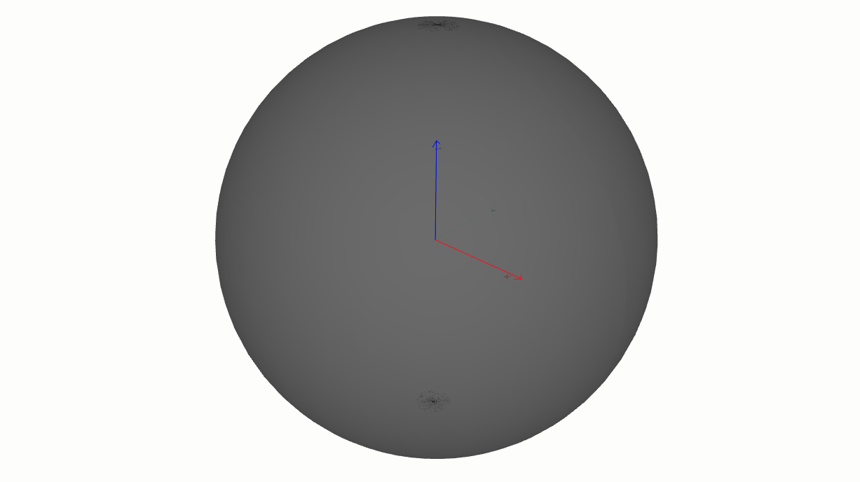
SphericalSurface3D#
To instanciate a SphericalSurface3D, you have to provide tree parameters: a frame, a radius and an optional name.
frame: This is a parameter passed to the constructor, representing a three-dimensional frame that describes the plane. The frame consists of an origin o and vectors u and v that define the plane, and w represents the normal vector to the plane. This implies that the plane is defined by a local coordinate system.
radius: This parameter represents the radius of the sphere.
name: An optional parameter representing the name of the plane. The default value is an empty string if not provided.
import volmdlr
from volmdlr import surfaces
from volmdlr.core import EdgeStyle

surface3d = surfaces.SphericalSurface3D(frame=volmdlr.OXYZ, radius=2, name='spherical_surface_name')
surface3d.plot(edge_style=EdgeStyle('orange'))
(Source code, png, hires.png, pdf)
RulledSurface3D#
This Class represents a three-dimensional ruled surface, which is a surface created by connecting points between two wires. To instanciate it, you need to provide 3 parameters: wire1, wire2`and `name.
wire1: This is a parameter passed to the constructor, representing the first wire defining the ruled surface. It is of type wires.Wire3D.
wire2: This is a parameter passed to the constructor, representing the second wire defining the ruled surface. Like wire1, it is of type wires.Wire3D.
name: An optional parameter representing the name of the ruled surface. The default value is an empty string if not provided.
import volmdlr
from volmdlr import surfaces
from volmdlr.core import EdgeStyle
#todo
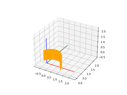
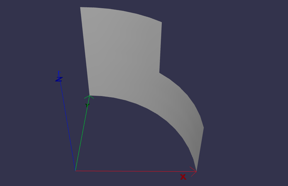
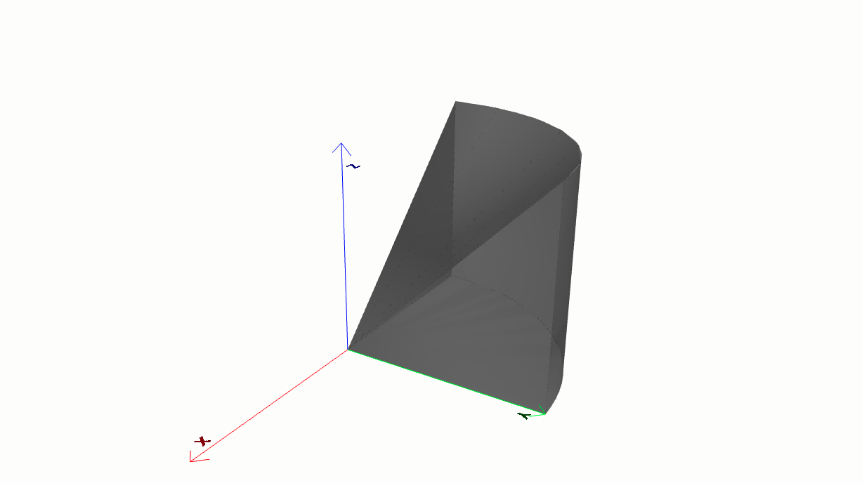
ExtrusionSurface3D#
This class represents a three-dimensional extrusion surface. It can be instanciated by providing:
edge: This is a parameter passed to the constructor, representing the edge that defines the curve to be extruded. It is of type Union[edges.FullArcEllipse3D, edges.BSplineCurve3D], indicating that the edge is expected to be an Ellipse or a B-Spline curve. But The edge can also be either a Wire3D or a Contour3D
direction: This is a parameter passed to the constructor, representing the axis of extrusion. It is of type volmdlr.Vector3D. The direction vector is normalized to ensure it is a unit vector.
name: An optional parameter representing the name of the extrusion surface. The default value is an empty string if not provided.
import volmdlr
from volmdlr import edges, surfaces, curves
from volmdlr.core import EdgeStyle

circle3d = curves.Circle3D(volmdlr.OXYZ, 1)

arc3d = edges.Arc3D(circle3d, start=circle3d.point_at_abscissa(0.2),
                    end=circle3d.point_at_abscissa(2.5))

surface = surfaces.ExtrusionSurface3D(arc3d, volmdlr.Z3D)

surface.plot(edge_style=EdgeStyle('orange'))
(Source code, png, hires.png, pdf)
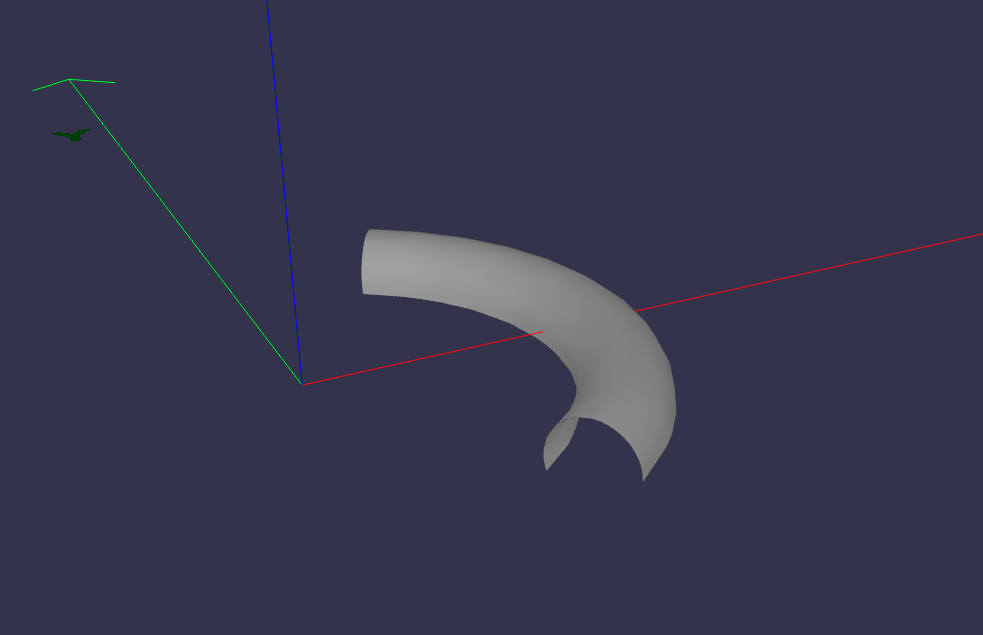
RevolutionSurface3D#
RevolutionSurface3D represents a three-dimensional surface of revolution. To instanciate it, it is needed to provide:
`edge: This is a parameter passed to the constructor, representing the edge that defines the profile curve of the surface of revolution. It is of type edges.Edge, indicating that it is expected to be an edge.
axis_point: This is a parameter passed to the constructor, representing the placement of the axis of revolution. It is of type volmdlr.Point3D.
axis: This is a parameter passed to the constructor, representing the axis of revolution. It is of type volmdlr.Vector3D. The axis vector is normalized to ensure it is a unit vector.
name: An optional parameter representing the name of the revolution surface. The default value is an empty string if not provided.
import math
import volmdlr
from volmdlr import edges, wires, surfaces
from volmdlr.core import EdgeStyle

linesegment = edges.LineSegment3D(volmdlr.Point3D(0.5, 0, 0), volmdlr.Point3D(0.5, 0, 0.5))

arc = edges.Arc3D.from_3_points(volmdlr.Point3D(0.5, 0, 0.5),
                volmdlr.Point3D(0.3 + 0.2 * math.cos(math.pi / 6), 0, 0.5 + 0.2 * math.sin(math.pi / 6)),
                volmdlr.Point3D(0.3 + 0.2 * math.cos(math.pi / 3), 0, 0.5 + 0.2 * math.sin(math.pi / 3)))

wire = wires.Wire3D([linesegment, arc])
axis_point = volmdlr.O3D
axis = volmdlr.Z3D
surface = surfaces.RevolutionSurface3D(wire, axis_point, axis)
surface.plot(edge_style=EdgeStyle('orange'))
(Source code, png, hires.png, pdf)
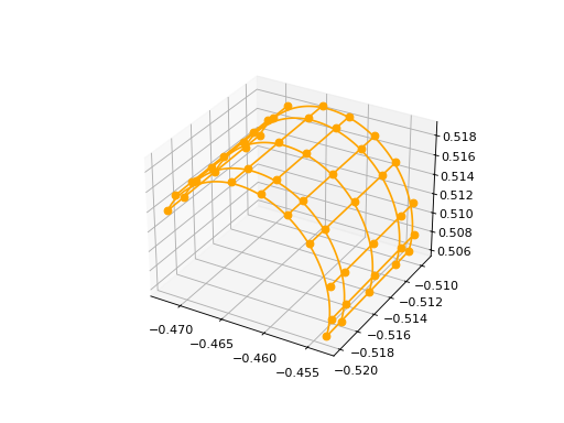
BSplineSurface3D#
BsplineSurface3D Represents a three-dimensional B-spline surface. To instanciate it, it is needed to provide:
degree_u: Represents the degree of the B-spline curve in the u direction.
degree_v: Represents the degree of the B-spline curve in the v direction.
control_points: Represents a list of 3D control points that define the shape of the surface. The control points are of type List[volmdlr.Point3D].
nb_u: Represents the number of control points in the u direction.
nb_v: Represents the number of control points in the v direction.
u_multiplicities: Represents a list of multiplicities for the knots in the u direction.
v_multiplicities: Represents a list of multiplicities for the knots in the v direction.
u_knots: Represents a list of knots in the u direction. The knots are real numbers that define the position of the control points along the u direction.
v_knots: Represents a list of knots in the v direction. The knots are real numbers that define the position of the control points along the v direction.
weights: This is an optional parameter representing a list of weights for the control points. The weights can be used to adjust the influence of each control point on the shape of the surface. The default value is None.
name: An optional parameter representing the name of the B-spline surface. The default value is an empty string if not provided.
from volmdlr import surfaces
from volmdlr.core import EdgeStyle
import numpy as np

bsp = surfaces.BSplineSurface3D(3, 3, np.array([
        [-0.47224769, -0.50977339,  0.51416422], [-0.47115651, -0.50983955,  0.51600901], [-0.46856059, -0.50991921,  0.51817403],
        [-0.46431341, -0.50995821,  0.51910384], [-0.46105775, -0.50995121,  0.51876123], [-0.45806846, -0.5099087 ,  0.51741441],
        [-0.45565101, -0.50983505,  0.51520204], [-0.45352158, -0.5097055 ,  0.51140362], [-0.45340494, -0.50958741,  0.50802068],
        [-0.45405263, -0.50951481,  0.5059723 ], [-0.47225024, -0.51143904,  0.51410599], [-0.47115906, -0.5115052 ,  0.51595078],
        [-0.46856313, -0.51158486,  0.51811579], [-0.46431596, -0.51162386,  0.51904561], [-0.4610603 , -0.51161686,  0.518703  ],
        [-0.458071  , -0.51157434,  0.51735618], [-0.45565355, -0.51150069,  0.51514381], [-0.45352413, -0.51137115,  0.51134539],
        [-0.45340749, -0.51125306,  0.50796245], [-0.45405517, -0.51118046,  0.50591406], [-0.47225533, -0.51477033,  0.51398953],
        [-0.47116415, -0.51483649,  0.51583431], [-0.46856823, -0.51491615,  0.51799933], [-0.46432105, -0.51495515,  0.51892915],
        [-0.46106539, -0.51494815,  0.51858653], [-0.4580761 , -0.51490564,  0.51723971], [-0.45565865, -0.51483199,  0.51502734],
        [-0.45352922, -0.51470245,  0.51122892], [-0.45341258, -0.51458435,  0.50784598], [-0.45406027, -0.51451175,  0.5057976 ],
        [-0.47226043, -0.51810162,  0.51387306], [-0.47116925, -0.51816779,  0.51571785], [-0.46857332, -0.51824745,  0.51788287],
        [-0.46432615, -0.51828645,  0.51881268], [-0.46107049, -0.51827945,  0.51847007],
        [-0.45808119, -0.51823693,  0.51712325], [-0.45566374, -0.51816328,  0.51491088], [-0.45353431, -0.51803374,  0.51111246],
        [-0.45341768, -0.51791565,  0.50772952], [-0.45406536, -0.51784304,  0.50568114], [-0.47226297, -0.51976727,  0.51381483],
        [-0.47117179, -0.51983343,  0.51565961], [-0.46857587, -0.51991309,  0.51782463], [-0.46432869, -0.51995209,  0.51875445],
        [-0.46107303, -0.51994509,  0.51841183], [-0.45808374, -0.51990258,  0.51706502], [-0.45566629, -0.51982893,  0.51485265],
        [-0.45353686, -0.51969939,  0.51105423], [-0.45342022, -0.5195813 ,  0.50767128], [-0.4540679 , -0.51950869,  0.5056229 ]]),
                                u_multiplicities=np.array([4, 1, 4]),
                                v_multiplicities=np.array([4, 1, 1, 1, 1, 1, 1, 4]),
                                u_knots=np.array([0. , 0.5, 1. ]),
                                v_knots=np.array([0., 0.22112628, 0.33220626, 0.4436676 , 0.55534525, 0.66698786, 0.77835802, 1.]),
                                nb_u=5, nb_v=10)

bsp.plot(edge_style=EdgeStyle('orange'))
(Source code, png, hires.png, pdf)
Faces#
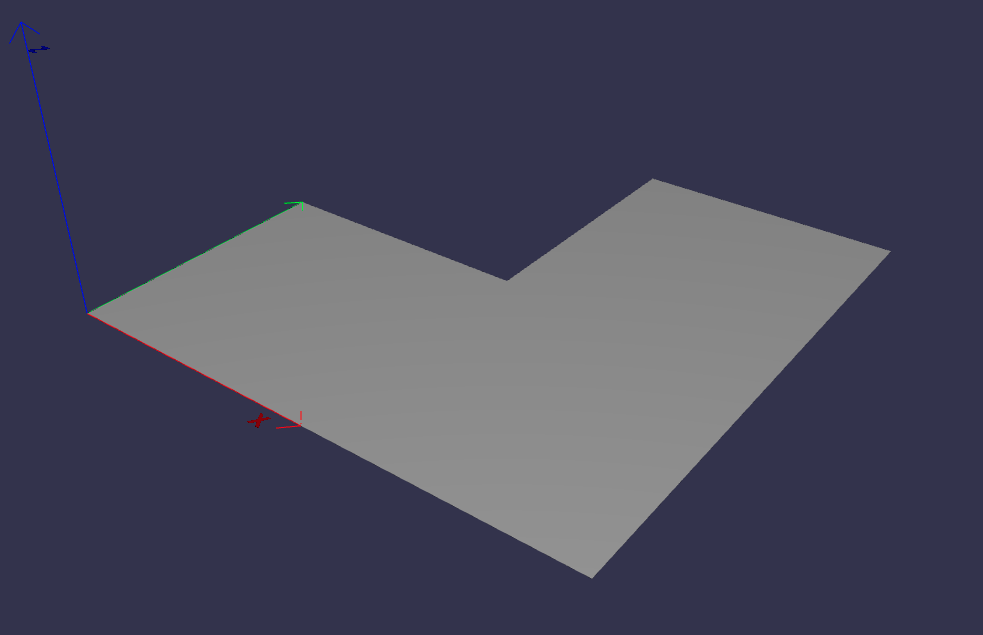
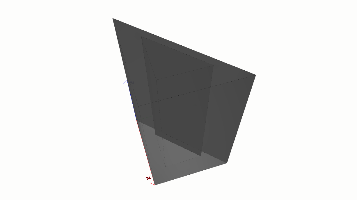
PlaneFace3D#
To create a PlaneFace3D, you need to provide two arguments: a surface3d and a surface2d.
For the surface3d, you must create a Plane3D, which is constructed using a Frame3D and an optional name parameter.
For the surface2d, you instantiate it by providing an outer contour in 2D, which will serve as the outer border of the face. Additionally, you need to provide a list of inner contours in 2D, representing any holes within the face, if applicable. The surface2d can also have an optional name argument.
Ensure to provide the necessary information for both surface3d and surface2d to successfully create the PlaneFace3D.
import volmdlr
from volmdlr import edges, curves, surfaces, wires, faces
from volmdlr.core import EdgeStyle

surface3d = surfaces.Plane3D(volmdlr.Frame3D(volmdlr.Point3D(0.0, 0.0, 0.0), volmdlr.Vector3D(1.0, 0.0, 0.0),
                                            volmdlr.Vector3D(0.0, 1.0, 0.0), volmdlr.Vector3D(0.0, 0.0, 1.0)))

outer_contour2d = wires.Contour2D.from_points(points=[volmdlr.Point2D(0., 0.), volmdlr.Point2D(2, 0),
                                                     volmdlr.Point2D(2, 2), volmdlr.Point2D(1, 2),
                                                     volmdlr.Point2D(1, 1), volmdlr.Point2D(0, 1)])
inner_contours2d = []
surface2d = surfaces.Surface2D(outer_contour=outer_contour2d, inner_contours=inner_contours2d)

plane_face = faces.PlaneFace3D(surface3d=surface3d, surface2d=surface2d)

plane_face.babylonjs()
Triangle3D#
A Triangle3D receives three mandatory arguments: The three vertices points of the triaangle, along with a last optional name argument.
import volmdlr
from volmdlr import edges, curves, surfaces, wires, faces
from volmdlr.core import EdgeStyle

triangle3d = faces.Triangle3D(volmdlr.Point3D(0., 0., 1.0), volmdlr.Point3D(2, 0, 0.2), volmdlr.Point3D(2, 2, 3.0))
triangle3d.babylonjs()

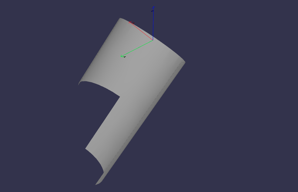
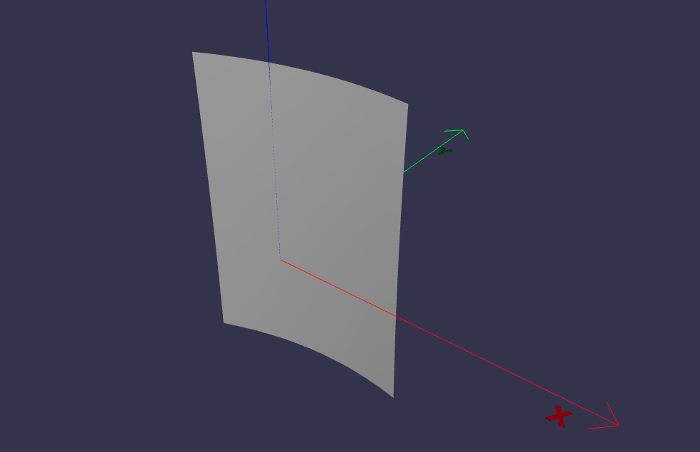
CylindricalFace3D#
To create a CylindricalFace3D, you need to provide two arguments: a surface3d and a surface2d.
For the surface3d, you must create a CylindricalSurface3D, which is constructed using a Frame3D, a float value for the cylinder radius and an optional name parameter.
For the surface2d, you instantiate it by providing an outer contour in 2D, which will serve as the outer border of the face. Additionally, you need to provide a list of inner contours in 2D, representing any holes within the face, if applicable. The surface2d can also have an optional name argument.
Ensure to provide the necessary information for both surface3d and surface2d to successfully create the CylindricalFace3D.
import volmdlr
from volmdlr import edges, curves, surfaces, wires, faces
from volmdlr.core import EdgeStyle

vector1 = volmdlr.Vector3D(1, 1, 1)
vector1 = vector1.unit_vector()
vector2 = vector1.deterministic_unit_normal_vector()
vector3 = vector1.cross(vector2)
frame = volmdlr.Frame3D(volmdlr.O3D, vector1, vector2, vector3)

surface3d = surfaces.CylindricalSurface3D(frame, 1)

outer_contour2d = wires.Contour2D.from_points(points=[volmdlr.Point2D(0., 0.), volmdlr.Point2D(4, 0),
                                                                 volmdlr.Point2D(4, 4), volmdlr.Point2D(2, 4),
                                                                 volmdlr.Point2D(2, 2), volmdlr.Point2D(0, 2)])
surface2d = surfaces.Surface2D(outer_contour=outer_contour2d, inner_contours=[])

face3d = faces.CylindricalFace3D(surface3d, surface2d)

face3d.babylonjs()
ToroidalFace3D#
To create a ToroidalFace3D, you need to provide two arguments: a surface3d and a surface2d.
For the surface3d, you must create a ToroidalSurface3D, which is constructed using three main arguments:
Frame3D: the three dimensional frame where the toroidal face is at.
tore_radius: The distance from the center of the torus to the center of the tube (the larger radius).
small_radius: The radius of the tube (the smaller radius).
For the surface2d, you instantiate it by providing an outer contour in 2D, which will serve as the outer border of the face. Additionally, you need to provide a list of inner contours in 2D, representing any holes within the face, if applicable. The surface2d can also have an optional name argument.
Ensure to provide the necessary information for both surface3d and surface2d to successfully create the ToroidalFace3D.
import volmdlr
from volmdlr import edges, curves, surfaces, wires, faces
from volmdlr.core import EdgeStyle


surface3d = surfaces.ToroidalSurface3D(volmdlr.OXYZ, major_radius=0.2, minor_radius=0.03, name='optional_toroidalsurface3d\'s_name')

points = [volmdlr.Point2D(-1.0, 0), volmdlr.Point2D(1, 0), volmdlr.Point2D(1, 3.5), volmdlr.Point2D(-1, 3.5)]
outer_contour2d = wires.Contour2D.from_points(points=points)
surface2d = surfaces.Surface2D(outer_contour=outer_contour2d, inner_contours=[])

toroidal_face3d = faces.ToroidalFace3D(surface3d, surface2d)

toroidal_face3d.babylonjs()
ConicalFace3D#
To create a ConicalFace3D, you need to provide two arguments: a surface3d and a surface2d.
For the surface3d, you must create a ConicalSurface3D, which is constructed using two main arguments:
Frame3D: the three dimensional frame where the conical face is at. The frame.w is the cone’s axis
semi_angle: The semi-angle of a cone refers to the angle between the central axis of the cone and a line connecting the apex (top) of the cone to a point on the base.
For the surface2d, you instantiate it by providing an outer contour in 2D, which will serve as the outer border of the face. Additionally, you need to provide a list of inner contours in 2D, representing any holes within the face, if applicable. The surface2d can also have an optional name argument.
Ensure to provide the necessary information for both surface3d and surface2d to successfully create the ConicalFace3D.
import volmdlr
from volmdlr import edges, curves, surfaces, wires, faces
from volmdlr.core import EdgeStyle


surface3d = surfaces.ConicalSurface3D(volmdlr.OXYZ, semi_angle=0.2, name='optional_conicalsurface3d\'s_name')

points = [volmdlr.Point2D(-1.0, 0.0), volmdlr.Point2D(3.0, 0.0), volmdlr.Point2D(3.0, 4.0), volmdlr.Point2D(-1.0, 4.0)]
outer_contour2d = wires.Contour2D.from_points(points=points)
surface2d = surfaces.Surface2D(outer_contour=outer_contour2d, inner_contours=[])

toroidal_face3d = faces.ConicalFace3D(surface3d, surface2d)

toroidal_face3d.babylonjs()
SphericalFace3D#
To create a SphericalFace3D, you need to provide two arguments: a surface3d and a surface2d.
For the surface3d, you must create a SphericalSurface3D, which is constructed using two main arguments:
Frame3D: the three dimensional frame where the spherical face is at. The frame.origin is the spheres’ center.
radius: the radius of the sphere.
For the surface2d, you instantiate it by providing an outer contour in 2D, which will serve as the outer border of the face. Additionally, you need to provide a list of inner contours in 2D, representing any holes within the face, if applicable. The surface2d can also have an optional name argument.
Ensure to provide the necessary information for both surface3d and surface2d to successfully create the ConicalFace3D.
import volmdlr
from volmdlr import edges, curves, surfaces, wires, faces
from volmdlr.core import EdgeStyle


surface3d = surfaces.SphericalSurface3D(volmdlr.OXYZ, radius=0.2, name='optional_sphericalsurface3d\'s_name')

points = [volmdlr.Point2D(0.0, 0.0), volmdlr.Point2D(2.5, 0.0), volmdlr.Point2D(2.5, 1.5), volmdlr.Point2D(0.0, 1.5)]
outer_contour2d = wires.Contour2D.from_points(points=points)
surface2d = surfaces.Surface2D(outer_contour=outer_contour2d, inner_contours=[])

spherical_face3d = faces.SphericalFace3D(surface3d, surface2d)

spherical_face3d.babylonjs()
RuledFace3D#
ExtrusionFace3D#
To create a ExtrusionFace3D, you need to provide two arguments: a surface3d and a surface2d.
For the surface3d, you must create a ExtrusionSurface3D, which is constructed using two main arguments:
edge: the edge to be estruded.
direction: The extrusion direction vector.
For the surface2d, you instantiate it by providing an outer contour in 2D, which will serve as the outer border of the face. Additionally, you need to provide a list of inner contours in 2D, representing any holes within the face, if applicable. The surface2d can also have an optional name argument.
Ensure to provide the necessary information for both surface3d and surface2d to successfully create the ExtrusionFace3D.
import volmdlr
from volmdlr import edges, curves, surfaces, wires, faces
from volmdlr.core import EdgeStyle


arc2 = volmdlr.edges.Arc3D(curves.Circle3D(volmdlr.OXYZ, 1), volmdlr.Point3D(1, 0, 0), volmdlr.Point3D(0, 1, 0))
surface3d = surfaces.ExtrusionSurface3D(edge=arc2, direction=volmdlr.Z3D)

outer_contour2d = wires.Contour2D.from_points(points=[volmdlr.Point2D(0., 0.), volmdlr.Point2D(1, 0),
                                                                 volmdlr.Point2D(1, 1), volmdlr.Point2D(0.5, 1),
                                                                 volmdlr.Point2D(0.5, 0.5), volmdlr.Point2D(0, 0.5)])
inner_contours2d = []
surface2d = surfaces.Surface2D(outer_contour=outer_contour2d, inner_contours=inner_contours2d)

face = faces.ExtrusionFace3D(surface3d, surface2d)

face.babylonjs()
RevolutionFace3D#
To create a RevolutionFace3D, you need to provide two arguments: a surface3d and a surface2d.
For the surface3d, you must create a RevolutionSurface3D, which is constructed using three main arguments:
edge: the revolution edge.
axis_point: revolution’s axis point.
axis: The axis of revolution.
For the surface2d, you instantiate it by providing an outer contour in 2D, which will serve as the outer border of the face. Additionally, you need to provide a list of inner contours in 2D, representing any holes within the face, if applicable. The surface2d can also have an optional name argument.
Ensure to provide the necessary information for both surface3d and surface2d to successfully create the RevolutionFace3D.
import volmdlr
from volmdlr import edges, curves, surfaces, wires, faces
from volmdlr.core import EdgeStyle

fullarc = edges.FullArc3D(circle=curves.Circle3D(
             volmdlr.Frame3D(
                 volmdlr.Point3D(0.003516498393599, -0.01267818173491, 0.0), volmdlr.Vector3D(1.0, 0.0, 0.0),
                 volmdlr.Vector3D(0.0, 1.0, 0.0), volmdlr.Vector3D(0.0, 0.0, 1.0)), radius=0.024102542625267),
                 start_end=volmdlr.Point3D(0.027619041018866, -0.01267818173491, 0.0))

surface3d = surfaces.RevolutionSurface3D(
     edge=fullarc, axis_point=volmdlr.Point3D(0, 0, 0), axis=volmdlr.Vector3D(0, 1, 0))


outer_contour2d = wires.Contour2D(primitives=[edges.LineSegment2D(volmdlr.Point2D(0.0, 0.023550776716126855),
                                                       volmdlr.Point2D(6.283185307179586, 0.023550776716126855)),
                                   edges.LineSegment2D(volmdlr.Point2D(6.283185307179586, 0.023550776716126855),
                                                       volmdlr.Point2D(6.283185307179586, 0.016162537035284696)),
                                   edges.LineSegment2D(volmdlr.Point2D(6.283185307179586, 0.016162537035284696),
                                                       volmdlr.Point2D(0.0, 0.016162537035284696)),
                                   edges.LineSegment2D(volmdlr.Point2D(0.0, 0.016162537035284696),
                                                       volmdlr.Point2D(0.0, 0.023550776716126855))])
inner_contours2d = []
surface2d = surfaces.Surface2D(outer_contour=outer_contour2d, inner_contours=inner_contours2d)
face = faces.RevolutionFace3D(surface3d, surface2d)

face.babylonjs()
BSplineFace3D#
To create a RevolutionFace3D, you need to provide two arguments: a surface3d and a surface2d.
1. For the surface3d, you must create a BSplineSurface3D, for which we have to provide the necessary parameters, such as the degrees (degree_u and degree_v), control points (instances of Point3D), number of control points in u and v directions (nb_u and nb_v), knot multiplicities, knot vectors (u_knots and v_knots), optional weights, and name.
For the surface2d, you instantiate it by providing an outer contour in 2D, which will serve as the outer border of the face. Additionally, you need to provide a list of inner contours in 2D, representing any holes within the face, if applicable. The surface2d can also have an optional name argument.
Ensure to provide the necessary information for both surface3d and surface2d to successfully create the RevolutionFace3D.
import volmdlr
from volmdlr import edges, curves, surfaces, wires, faces
from volmdlr.core import EdgeStyle

control_points = [volmdlr.Point3D(0, 0, 0), volmdlr.Point3D(0.1, 0.02, 0), volmdlr.Point3D(0.2, 0.02, 0),
                  volmdlr.Point3D(0, 0, 0.15), volmdlr.Point3D(0.1, 0.02, 0.15), volmdlr.Point3D(0.2, 0.02, 0.15),
                  volmdlr.Point3D(0, 0, 0.3), volmdlr.Point3D(0.1, 0.021, 0.3), volmdlr.Point3D(0.2, 0.022, 0.3)
       ]

surface3d = surfaces.BSplineSurface3D(degree_u=2, degree_v=2, control_points=control_points, nb_u=3, nb_v=3,
                                    u_multiplicities=[1, 2, 2, 1], v_multiplicities=[1, 2, 2, 1],
                                    u_knots=[0.1, 0.3, 0.5, 0.7], v_knots=[0.1, 0.3, 0.5, 0.7])

outer_contour2d = wires.Contour2D.from_points(points=[volmdlr.Point2D(0, 0), volmdlr.Point2D(1, 0),
                                                      volmdlr.Point2D(1, 1), volmdlr.Point2D(0, 1)])
inner_contours2d = []
surface2d = surfaces.Surface2D(outer_contour=outer_contour2d, inner_contours=inner_contours2d)

face = faces.BSplineFace3D(surface3d, surface2d)

face.babylonjs()
Shells#
A shell is defined as a collection of connected faces. A Shell can a ClosedShell3D or an OpenShell3D. it receives as parameters a list of faces (instances of Face3D), optional color, alpha (transparency), name, and a bounding box.
In the example bellow, it is shown the definition of the shell’s lateral faces.
import volmdlr
from volmdlr import edges, curves, surfaces, wires, faces, shells
from volmdlr.core import EdgeStyle
import math

polygon1_vol1 = wires.ClosedPolygon3D([volmdlr.Point3D(-0.1, -0.05, 0), volmdlr.Point3D(-0.15, 0.1, 0),
                    volmdlr.Point3D(0.05, 0.2, 0), volmdlr.Point3D(0.12, 0.15, 0), volmdlr.Point3D(0.1, -0.02, 0)])

polygon2_vol1 = polygon1_vol1.rotation(volmdlr.O3D, volmdlr.Z3D, math.pi).translation(0.2*volmdlr.Z3D)
polygon3_vol1 = polygon2_vol1.rotation(volmdlr.O3D, volmdlr.Z3D, math.pi/8).translation(0.1*(volmdlr.Z3D+volmdlr.X3D+volmdlr.Y3D))
faces_ = [faces.Triangle3D(*points)
        for points in polygon1_vol1.sewing(polygon2_vol1, volmdlr.X3D, volmdlr.Y3D)] + \
        [faces.Triangle3D(*points)
        for points in polygon2_vol1.sewing(polygon3_vol1, volmdlr.X3D, volmdlr.Y3D)]
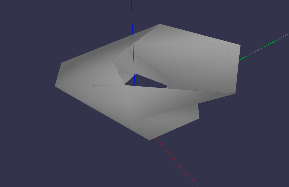
OpenShell3D#
With these faces we can instantiate an OpenShell3D:
shell1 = shells.OpenShell3D(faces_)
shell1.babylonjs()
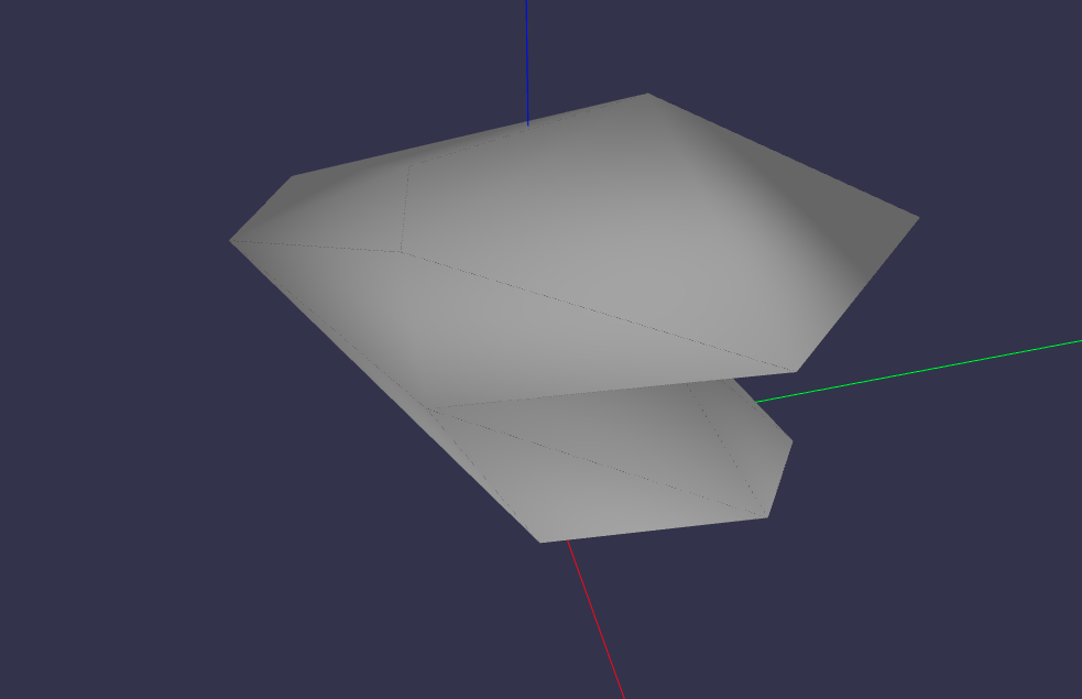
ClosedShell3D#
Then the bottom and top faces can be created so a closedshell3d can be instantiated:
bottom_surface3d = surfaces.Plane3D.from_plane_vectors(volmdlr.O3D, volmdlr.X3D, volmdlr.Y3D)
bottom_surface2d = surfaces.Surface2D(polygon1_vol1.to_2d(volmdlr.O3D, volmdlr.X3D, volmdlr.Y3D),[])

top_surface3d = surfaces.Plane3D.from_plane_vectors(0.3*volmdlr.Z3D, volmdlr.X3D, volmdlr.Y3D)
top_surface2d = surfaces.Surface2D(polygon3_vol1.to_2d(volmdlr.O3D, volmdlr.X3D, volmdlr.Y3D),[])

bottom_face = faces.PlaneFace3D(bottom_surface3d, bottom_surface2d)
top_face = faces.PlaneFace3D(top_surface3d, top_surface2d)
faces_ += [bottom_face, top_face]

shell1 = shells.ClosedShell3D(faces_)
shell1.babylonjs()
Primitives3D#
Block#
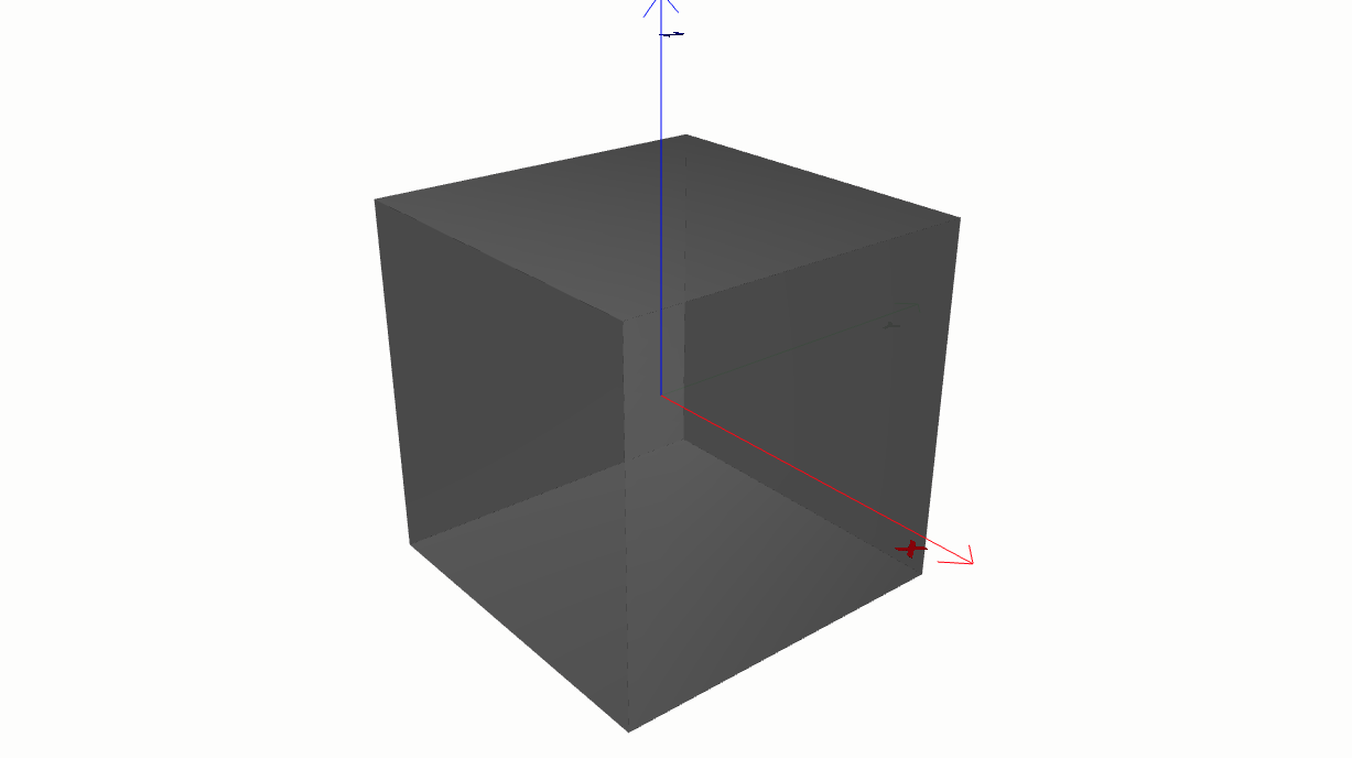
This class creates a block-shaped 3D object, by specifying its center, dimensions, color and other attributes. The constructor takes a frame, which represents the 3D frame for the block. This frame includes the origin (center of the block) and three vectors that define the edges of the block. The optional keyword arguments include color (RGB tuple representing the color of the block), alpha (opacity), and name (name of the block).
import volmdlr  # Import the necessary module
from volmdlr import primitives3d

# Define the 3D frame for the block
frame = volmdlr.Frame3D(
    origin=volmdlr.Point3D(0, 0, 0),  # Center of the block
    u=volmdlr.Vector3D(1, 0, 0),  # Vector defining one edge
    v=volmdlr.Vector3D(0, 1, 0),  # Vector defining another edge
    w=volmdlr.Vector3D(0, 0, 1)   # Vector defining the third edge
)

# Create a block instance
block = primitives3d.Block(frame, color=(0.5, 0.5, 0.5), alpha=0.8, name='MyBlock')
block.babylonjs()

# Now you have a block object with the specified attributes
# You can perform various operations with the block
more about the Block class in Primitives3d
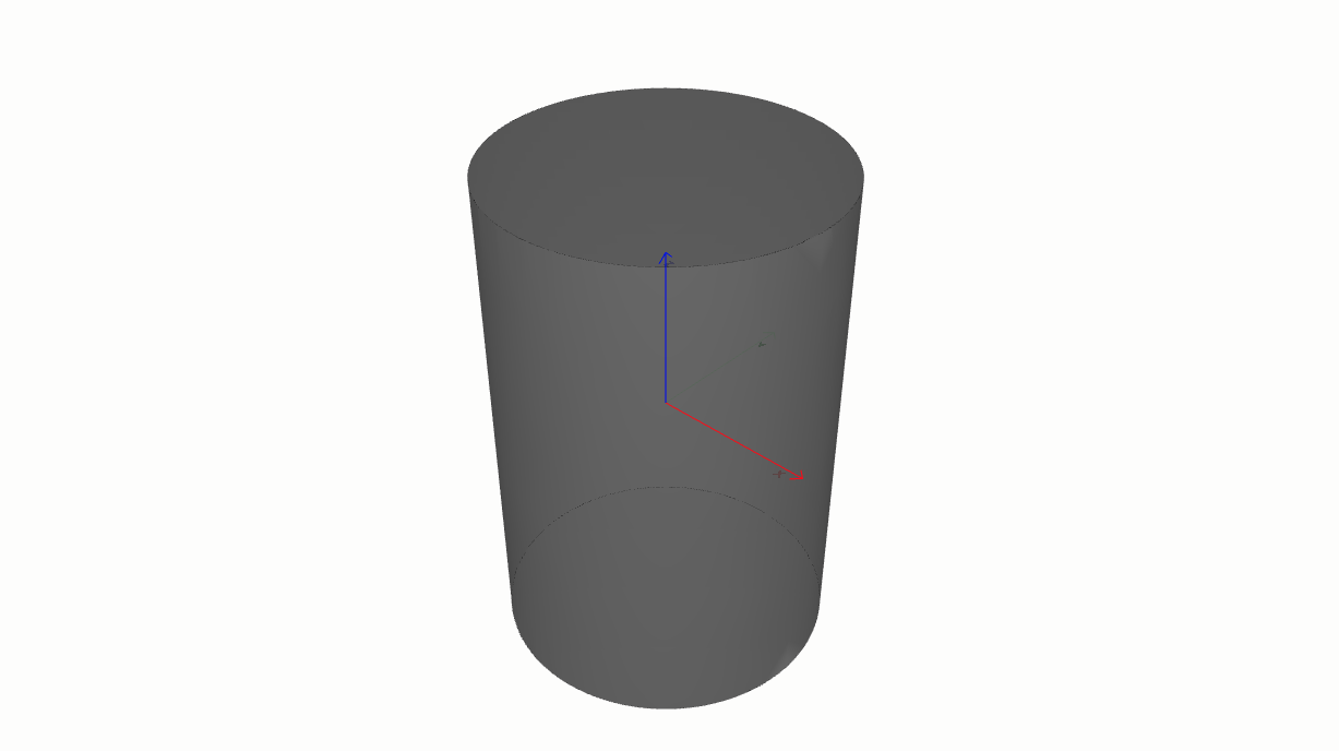
Cylinder#
The Cylinder class creates a Cylinder object using the following arguments:
frame: A 3D frame representing the orientation of the cylinder.
radius: The radius of the cylinder.
length: The length of the cylinder.
Optional keyword arguments include color, alpha, and name.
Here is how you can instantiate it:
import volmdlr
from volmdlr import primitives3d


# Define the 3D frame for the cylinder
frame = volmdlr.OXYZ

# Define cylinder parameters
radius = 1.0
length = 3.0

# Create a cylinder instance
cylinder = primitives3d.Cylinder(frame, radius, length, color=(0.5, 0.5, 0.5), alpha=0.8, name='MyCylinder')
cylinder.babylonjs()
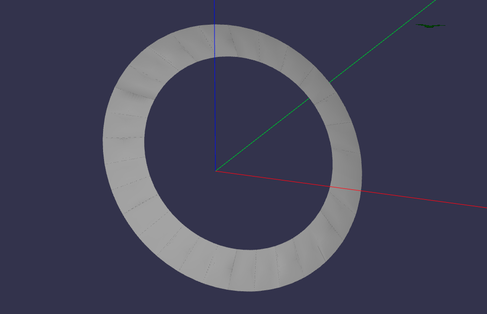
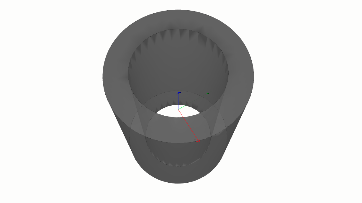
HollowCylinder#
The Hollow Cylinder class, as its name indicates, creates a HollowCylinder object using the following arguments:
frame: A 3D frame representing the orientation of the hollow cylinder.
inner_radius: The inner radius of the cylinder.
outer_radius: The outer radius of the cylinder.
length: The length of the cylinder.
Optional keyword arguments include color, alpha, and name.
Here is how you can instantiate it:
import volmdlr
from volmdlr import primitives3d

frame = volmdlr.OXYZ
inner_radius = 1.0
outer_radius = 1.5
length = 4.0

# Create a hollow cylinder instance
hollow_cylinder = primitives3d.HollowCylinder(frame, inner_radius, outer_radius, length,
                                              color=(0.5, 0.5, 0.5), alpha=0.8, name='MyHollowCylinder')
hollow_cylinder.babylonjs()
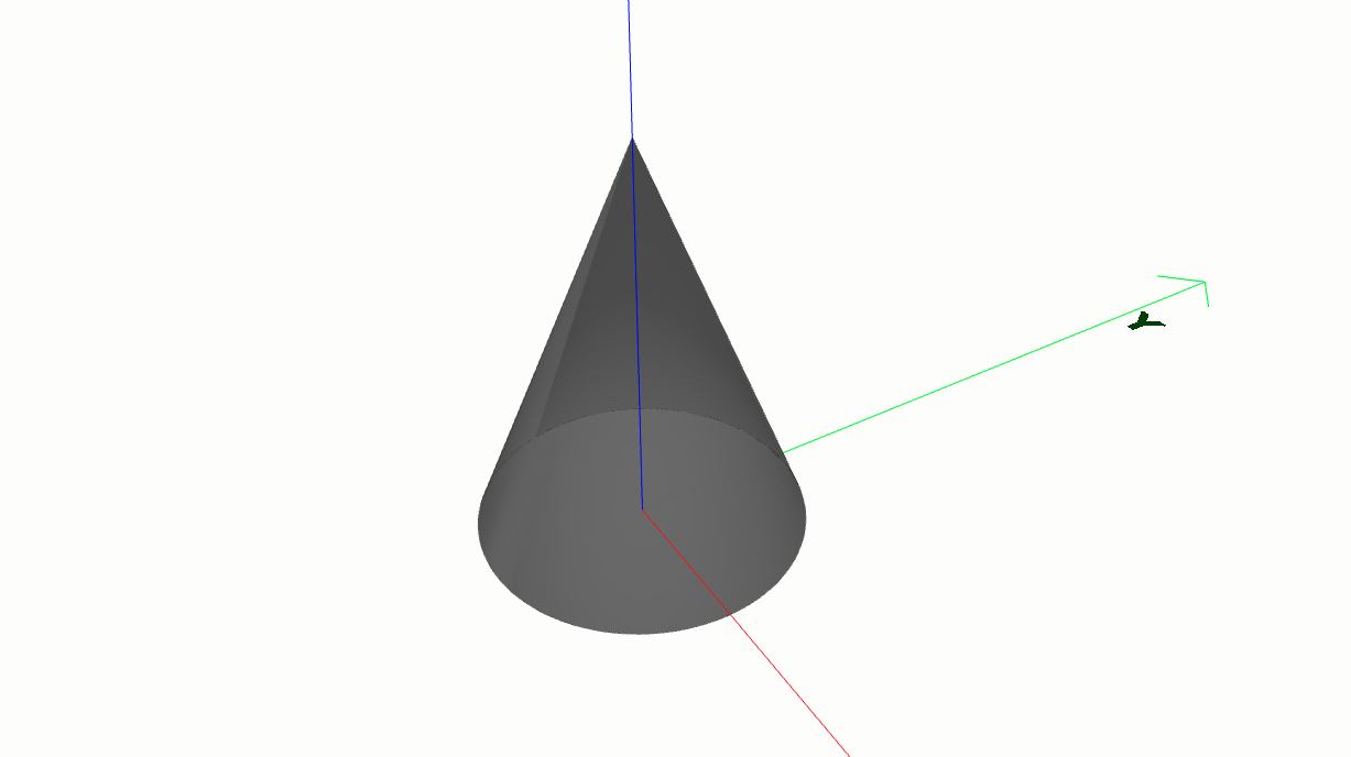
Cone#
The Clone class, as its name indicates, creates a Cone object using the following arguments:
frame: A 3D frame representing the orientation of the cone.
radius: The radius of the cone’s base.
length: The height of the cone.
Optional keyword arguments include color, alpha, and name.
Here is how you can instantiate it:
import volmdlr
from volmdlr import primitives3d

frame = volmdlr.OXYZ
radius = 0.2
length = 0.5
cone = primitives3d.Cone(frame=frame, radius = radius, length=length, color=(0.5, 0.5, 0.5), alpha=0.8, name='MyCone')
cone.babylonjs()
Sphere#
The Sphere class, as its name indicates, creates a Sphere centered at a given position with a specified radius. object using the following arguments:
center: A 3D point representing the center of the sphere.
radius: The radius of the sphere.
Here is how you can instantiate it:
import volmdlr
from volmdlr import primitives3d

# Define the center point of the sphere
center = volmdlr.Point3D(0, 0, 0)

# Define the radius of the sphere
radius = 2.0

# Create a sphere instance
sphere = primitives3d.Sphere(center, radius, color=(0.5, 0.5, 0.5), alpha=0.8, name='MySphere')
sphere.babylonjs()
RevolvedProfile#
RevolvedProfile class is used for creating a 3D object by revolving a 2D profile around an axis. To do so, you must provide the following attributes:
- The constructor takes several parameters:
frame: A 3D frame representing the orientation of the revolved profile.
contour2d: A 2D contour that defines the shape of the profile in the plane perpendicular to the axis.
axis_point: A point on the axis of revolution.
axis: The axis of revolution.
angle: The angle by which the profile should be revolved around the axis (default: 2 * π radians).
Optional keyword arguments include color, alpha, and name.
import volmdlr
from volmdlr import primitives3d
import math
# Define the 3D frame for the revolved profile
frame = volmdlr.OYZX

# Define the 2D contour to be revolved
contour2d = volmdlr.wires.Contour2D.from_points([volmdlr.Point2D(0, 0), volmdlr.Point2D(1, 0), volmdlr.Point2D(1, 1)])

# Define the axis of revolution
axis_point = volmdlr.Point3D(0, 0, 0)
axis = volmdlr.Vector3D(0, 0, 1)

# Create a revolved profile instance
revolved_profile = primitives3d.RevolvedProfile(frame, contour2d, axis_point, axis, angle=math.pi / 2,
                                                color=(0.5, 0.5, 0.5), alpha=0.8, name='MyRevolution')
revolved_profile.babylonjs()

# Now you have a revolved profile object with the specified attributes
# You can perform various operations with the revolved profile
ExtrutedProfile#
The ExtrudedProfile class represents an extrudred profille with an outer and inner contours.
Here’s an explanation of the class and an example of how it could be used:
- The constructor takes several parameters:
frame: A 3D frame representing the orientation of the extruded profile.
outer_contour2d: A 2D contour that defines the outer shape of the profile in the XY plane.
inner_contours2d: A list of 2D contours representing possible inner holes in the profile.
extrusion_length: The length by which the profile should be extruded along the specified axis.
Optional keyword arguments include color, alpha, and name.
Usage Example:
import volmdlr  # Import the necessary module
from volmdlr import primitives3d

# Define the 3D frame for the extruded profile
frame = volmdlr.Frame3D(
    origin=volmdlr.Point3D(0, 0, 0),
    u=volmdlr.Vector3D(1, 0, 0),
    v=volmdlr.Vector3D(0, 1, 0),
    w=volmdlr.Vector3D(0, 0, 1)
)

# Define the outer and inner 2D contours
outer_contour2d = volmdlr.wires.Contour2D.from_points([volmdlr.Point2D(0, 0), volmdlr.Point2D(1, 0), volmdlr.Point2D(1, 1)])
inner_contours2d = [volmdlr.wires.Contour2D.from_points([volmdlr.Point2D(0.3, 0.2), volmdlr.Point2D(0.8, 0.2), volmdlr.Point2D(0.8, 0.7)])]

# Create an extruded profile instance
extruded_profile = primitives3d.ExtrudedProfile(frame, outer_contour2d, inner_contours2d, extrusion_length=2.0, color=(0.5, 0.5, 0.5), alpha=0.8, name='MyExtrusion')
extruded_profile.babylonjs()

# Now you have an extruded profile object with the specified attributes
# You can perform various operations with the extruded profile
Sweep#
The Sweep class is used to create a 3D object by sweeping a 2D contour along a 3D wire.
The constructor takes several parameters:
contour2d: A 2D contour that defines the shape to be swept.
wire3d: A 3D wire along which the contour2d is swept.
Optional keyword arguments include color, alpha, and name.
import random
import volmdlr
from volmdlr import primitives3d
random.seed(2)
p1 = volmdlr.Point3D(0, 0, 0)
p2 = volmdlr.Point3D(-0.150, 0, 0)
p3 = volmdlr.Point3D(-0.150, 0.215, 0)
p4 = volmdlr.Point3D(-0.150, 0.215, -0.058)
p5 = volmdlr.Point3D(-0.220, 0.186, -0.042)
points = [p1, p2, p3, p4, p5]
radius = {1: 0.015, 2: 0.020, 3: 0.03}
current_point = p5
for i in range(6):
current_point += volmdlr.Point3D.random(-0.1, 0.3, -0.1, 0.3, -0.1, 0.3)
points.append(current_point)
radius[4 + i] = 0.01 + 0.03 * random.random()
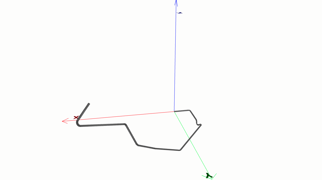
open_rounded_line_segements = primitives3d.OpenRoundedLineSegments3D(points, radius, adapt_radius=True, name='wire')
contour = wires.ClosedPolygon2D([volmdlr.Point2D(-0.004, -0.004), volmdlr.Point2D(0.004, -0.004),
volmdlr.Point2D(0.004, 0.004), volmdlr.Point2D(-0.004, 0.004)])
sweep = primitives3d.Sweep(contour, open_rounded_line_segements, color=(0.5, 0.5, 0.5), alpha=0.8, name='MySweep')
sweep.babylonjs()